The high cost of power has made
industries look into equipment to reduce power consumption.
Cooling Towers, heat exchanger, humidification and
ventilator are areas where a major saving is possible
at reasonable cost in the industries
.
The pioneering works of Aerotech have resulted
in 20% plus power saving and recovering the cost of
fan in short time.
Cast aluminum fans are consuming more power due to
low efficiency and heavy weight. The fans operate
at duty point all throughout 24 hours using excess
power, which can be saved by using
Aerotech aerodynamic design energy efficient
FRP hollow axial flow fans.
Aerotech has designed
and developed structurally strong FRP hollow fans
which are light-in-weight with help of USA based NACA*
computerized software, having more lift and low drag
airfoil shape, Engineered twist, optimized camber
to increase the fan efficiency which means resultant
low operating cost.
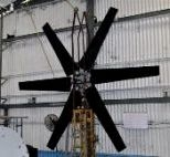
Aerotech method of Axial Flow Fan
design is based on data obtained from the combination
of the blade element theory, model fan tests in a
wind tunnel, and tests of full scale fans in the field.
The data are plotted as curves for fans of standard
theory form, making the actual operation in designing
the fan very short and simple. For the analysis or
design of special blade which is not conforming to
the standards, the modified blade element theory is
used, with airfoil section characteristics, which
give resultant powers and efficiencies checking the
standard model data.
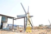
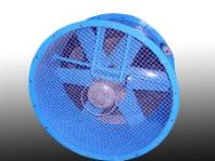
APPLICATION OF AXIAL FLOW FANS
The axial flow fans are widely used for providing
the required airflow for the heat & mass transfer
operations in various industrial equipment and processes.
These includes cooling tower for air conditioning
& ventilation, humidifiers in textile mills, air–heat
exchangers for various chemical processes, ventilation
& exhaust as in mining industry etc. all the major
industries use large number of axial flow fans operation,
such as:
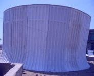
 Cooling Towers
Heat Exchangers
Humidifiers
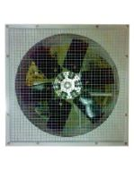
Ventilation
Industrial Air Circulator
Man Cooler
All type of Industrial Axial Flow Fan
Products Range:
|
» Energy efficient FRP Axial Flow Hollow fan Assemblies
» Aluminum Axial Flow Hollow fan Assemblies
» FRP fan Stack
» FRP Inlet Bell Mouth For ACC
» Drive Shaft
» Gear Box
|
| |
FRP Axial Flow Fans:
|
» Fan diameter : 250mm to 15000mm
» Air Flow : 0.5 M3/s to 2500m3/s
» Pressure : 1mm to 100mm
» Tip speed Limit : up to 70 M/s
|
| |
Aluminum Axial Flow Fans:
|
» Fan diameter : 250mm to 5500mm
» Air Flow : 0.5 M3/s to 400m3/s
» Pressure : 1mm to 100mm
» Tip speed Limit : up to 100 M/s
|
| |
Product Efficiency:
|
90% |
Raw Materials for Blades:
|
Epoxy / As per Client requirement |
| Raw Materials for Hub: |
Steel + Galvanized /SS/ As per Client requirement |
| Raw Materials for Hardware: |
SS-304 / SS-316/ As per Client requirement |
|
 |
 |
|
 |
 |
|
 |
 |
|
 |
 |
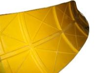
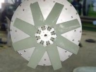
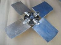
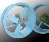
ENERGY EFFICIENT FRP AXIAL FLOW FAN
Fiber Reinforced Plastics (FRP) providing the
desired non-corrosive quality to the fan blades, resulting
in the operation of the fans even in the chemical
environment. Lightweight FRP fan also ensures a low
moment of inertia, minimum wear & stress on motor,
bearing and drive system. Hollow FRP blades is less
weightier than aluminum fan assembly, easy to Carry
and non-possibility of damage to fan & drive during
sudden stops due to light weight. Composite structural
design can be tailor made by using various glass fibers
(Glass cloth & woven roving mat and roving) in
right direction while moulding the fan blades with
Epoxy resin thus imparting the desired mechanical
strength by improving its industrial stability and
enhanced mechanical properties. Aerotech
design of the fan blades ensure more airflow, lower
noise level & less power consumption means high
efficiency. The AERODYNAMICALLY designed fan impeller
of the fans, fabricated by composite material can
be excellent alternative to ensure enhanced efficiency
& appropriate energy saving apart from wide gamut
of critical advantages.
ADVANTAGE OF FRP AXIAL FLOW FANS
The FRP fans offer certain critical advantages
as mentioned here under:
1.Optimal aerodynamic design of fan impellers to provide
higher efficiency for any specific application.
2.Reduction in overall weight of the fan, thereby
extending the life of mechanical drive system
3.Requires lower drive motor rating and light duty
bearing system.
4.Lower power consumption resulting in appreciable
energy savings.
5.FRP fan fabricated compression moulding/resin transfer
moulding technique would have uniform
dimensions and consistent quality.
6.Lower flow noise and mechanical noise level compared
to conventional metallic fans.
7.Longer life of the fan due to improved mechanical
strength.
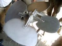
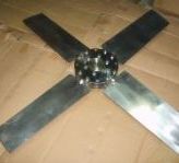
FRP HOLLOW FAN BLADES.
The basic purpose of a “fan” is to move
a mass of gas or vapor at the desired velocity. For
achieving this objective there is a slight increase
in the gas pressure across the fan rotor or impeller.
However main aim remains to move air or gas without
any appreciable increase in its pressure. The total
pressure developed by the fan is of the order of a
few millimeter of water gauge. A “blower”
which is also referred to as “fan” in
some literature deliver the gas or air with the appreciable
race in pressure to overcome some kind of resistance
in the flow. Some applications develop pressure of
the order or 1000 mm W.G. or more. An axial flow fan
stage in its simplest form consists of a rotor made
up of number of blades fitted to the hub. When it
is rotated by an electric motor or any other drive,
a flow is established through the rotor. The actions
of the rotor causes an increase in the stagnation
pressure of air or gas across it. A cylindrical casing
encloses the rotor. It receives the flow through a
P HOLLOW BLADE AERODYNAMIC DESIGN.
As mentioned previously the choice of correct twist
and of special airfoil sections to reduce compressibility
losses are of major importance in modern fan blades
design. However other considerations still remain
to be studied with care if the efficiency of the blade
is to be kept at its maximum under severe operating
conditions.
CENTRIFUGAL AND AERODYNAMIC TWISTING
In variable-pitch fan as described later the blades
are turned in the hub about their longitudinal or
pitch-change axis. Clearly the mechanism provided
to produce this pitch change must be capable of exerting
sufficient force to overcome any mechanical or aerodynamic
opposing force set up by the blades themselves. It
will be useful then to see exactly what these force
are.
The “mechanical force” involved is known
as Centrifugal Twisting Moment (C.T.M)which as its
name implies is closely allied to the normal centrifugal
force acting on the blades when the fan is rotating
about the shaft . It is turning couple brought about
by the fact that the blade section are inclined at
an angle to the fan of rotation and results in the
natural tendency for any fan blade, when rotating
turned about its longitudinal axis towards zero pitch
so that the blades section are turned in to the fan
blade rotation .
THRUST AND TORQUE FORCES.
The main factor that determines the force developed
by an aerofoil section is the angle at which it is
inclined to the relative airflow, i.e. the angle of
attack in order, therefore, for the fan blade section
to develop the requisite aerodynamic force for propulsion,
each section along the blade must be inclined at the
appropriate angle of attack to the relative airflow
direction pertaining to the section hence knowing
angle of attack is a simple mater to indicate the
force developed as shown in figure 1) from which it
will be noted that the total blade angle of attack
and the helix angle
|